Universal Gear Operator
Replacement
Field installation instructions for the UGOR. Designed to replace most manual gearboxes on gang-operated switches from 69 kV to 500 kV. Safe, low-maintenance, high torque in both opening and closing directions. Holds position at any point in the travel arc.
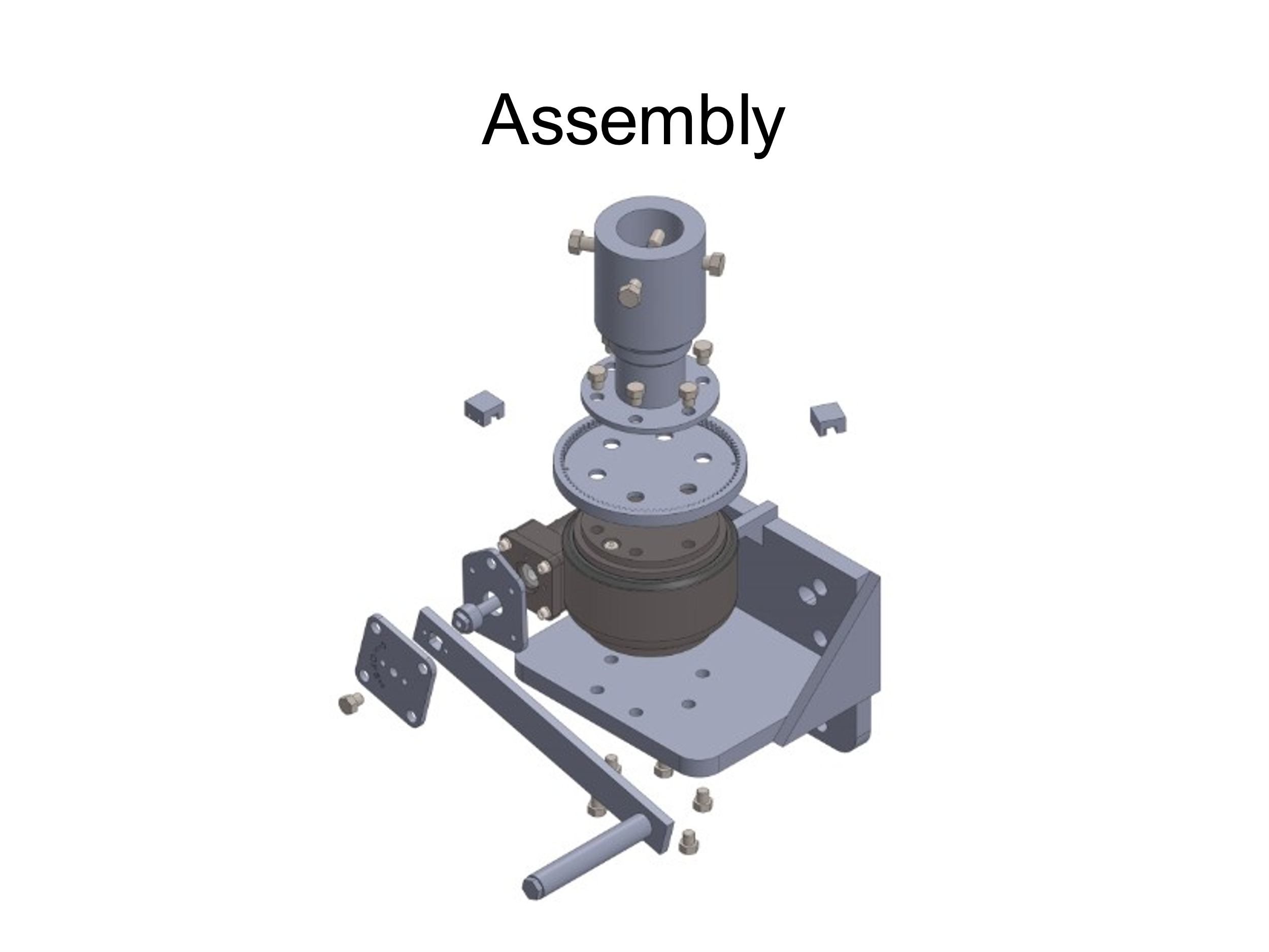
Verify box contents
Check the box against the assembly drawing before leaving the truck. Missing hardware is a second trip.
- Crank handle with mounted open/close plate, 3/8″ mounting bolt, and washers
- 4 piercing bolts
- 1 red open stop with brass set screw
- 1 green closed stop with brass set screw
- 4 aluminum shims (used for vertical alignment if needed)
Verify fit before removing the old gearbox
The switch will need to be opened and closed multiple times during installation and commissioning. Confirm clearance before work begins.
- Bolt pattern match Measure the existing operator bolt pattern — side to side and top to bottom. Confirm it matches one of the pre-drilled patterns on the UGOR back plate.
- Downpipe adapter size Confirm the adapter on the UGOR matches your downpipe: 2″ or 2½″. When mounted in the correct location, the bottom of the downpipe should reach the bottom of the adapter.
Two options are available:
Remove the old gearbox and drill new holes in the mounting surface to match one of the pre-drilled bolt patterns on the UGOR back plate.
Provide Southern Switch with your bolt pattern dimensions. A new unit with a custom back plate will be fabricated and shipped to you.
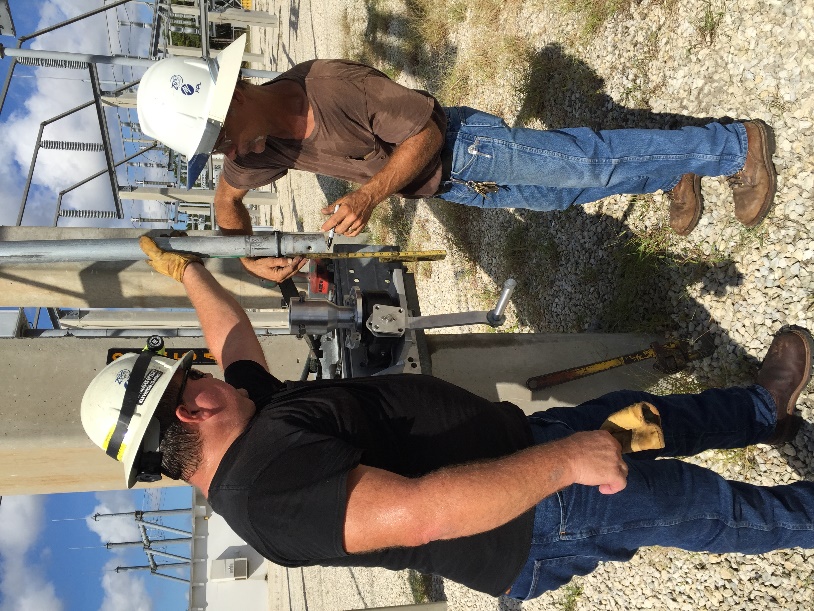
Remove old gearbox. Mount. Set stops. Commission.
Work through the steps in order. Do not pierce the downpipe until alignment and stop positions are confirmed.
- Close the switch, then remove the old gearbox Confirm the switch is in the fully closed position before removing the existing operator. Remove the grounding strap connection and set it aside — it will be reinstalled at the end.
- Check downpipe length against the adapter When the UGOR is mounted in the correct location, the bottom of the downpipe should reach the bottom of the adapter. If the adapter is too long for your downpipe, cut the adapter to the correct length. Note: If the existing downpipe is too short, a coupler is available from Southern Switch for an additional charge.
-
Trim the downpipe if needed
If material must be removed from the bottom of the downpipe to fit the adapter:
- Loosely mount the UGOR.
- Mark the downpipe at the correct length with a marker.
- Cut with a Sawzall or hacksaw.
- Remove the UGOR.
- Permanently mount with the downpipe fully inserted into the adapter.
- Snug piercing bolts — do not pierce yet Tighten the piercing bolts enough to hold the downpipe in position, but not enough to pierce it. Operate the handle and verify that the downpipe rotates in conjunction with the handle.
- Check vertical alignment of the downpipe Use a level. The downpipe must be vertical. If it is not, shim the UGOR out from the structure using the aluminum shims included in the box until vertical is achieved.
- Confirm switch is fully closed, then remove the open/close stops Using a hex key, remove both the open stop and the closed stop from the open/close plate. You will re-set their positions in the next steps.
- Mark the closed stop position With the switch in the fully closed position, use a black marker to mark the open/close plate at the leading edge of where the closed stop will contact the plate.
- Mark the open stop position Operate the switch to the fully open position. Mark the open/close plate at the leading edge of where the open stop will contact the plate.
- Confirm stop locations — two more cycles Open and close the switch at least two more times. Verify that the marks are consistent with full open and full close each time. Adjust if the marks do not repeat precisely.
- Set and secure the stops Place the open stop (red) and closed stop (green) on the open/close plate at the marked positions. Secure each stop using the hex key and brass set screws.
- Pierce the downpipe Tighten the piercing bolts until they fully penetrate the downpipe wall.
- Commissioning — open and close multiple times Operate the switch through full open and full close multiple times. Confirm that the stops engage correctly at both ends of travel and that the switch operation is smooth and properly aligned throughout the stroke.
- Reinstall grounding straps and identifying decals Reconnect the grounding strap removed in Step 1. Replace any identifying decals on the operator.
- Close switch and lock in position Return the switch to the closed position and lock. Installation complete.
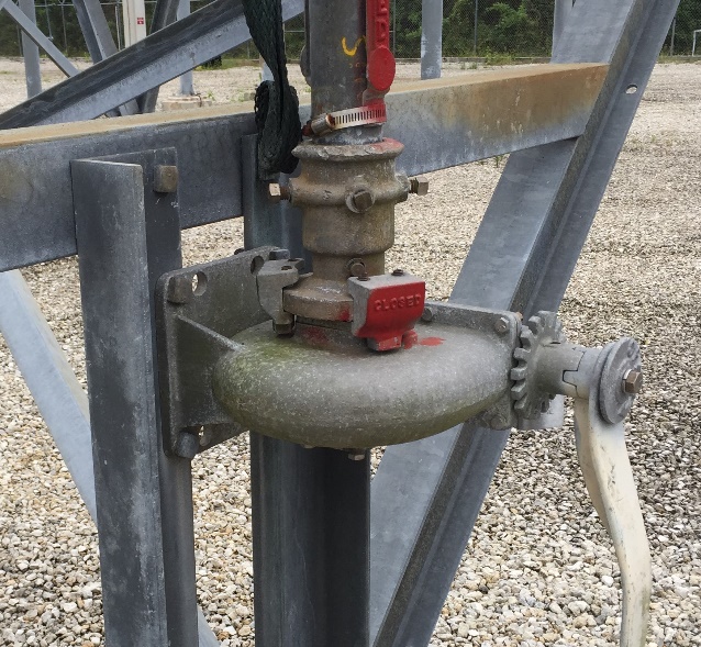
UGOR installed and in service
Call (727) 789-0951 or email info@southernswitch.com. Need a custom back plate or a downpipe coupler? Contact us with your dimensions.